

Gear Reducer Ratio vs Output Speed Explained
Gear reducer ratio and output speed are directly connected, yet they are often misunderstood. Selecting the wrong ratio can result in improper machine speed, reduced torque, overheating, or premature failure.
This article explains how gear reducer ratio affects output speed, how to calculate it, and how to choose the correct ratio for your application.
What Is a Gear Reducer Ratio?
The gear reducer ratio describes how much the input speed is reduced before reaching the output shaft.
It is typically expressed as:
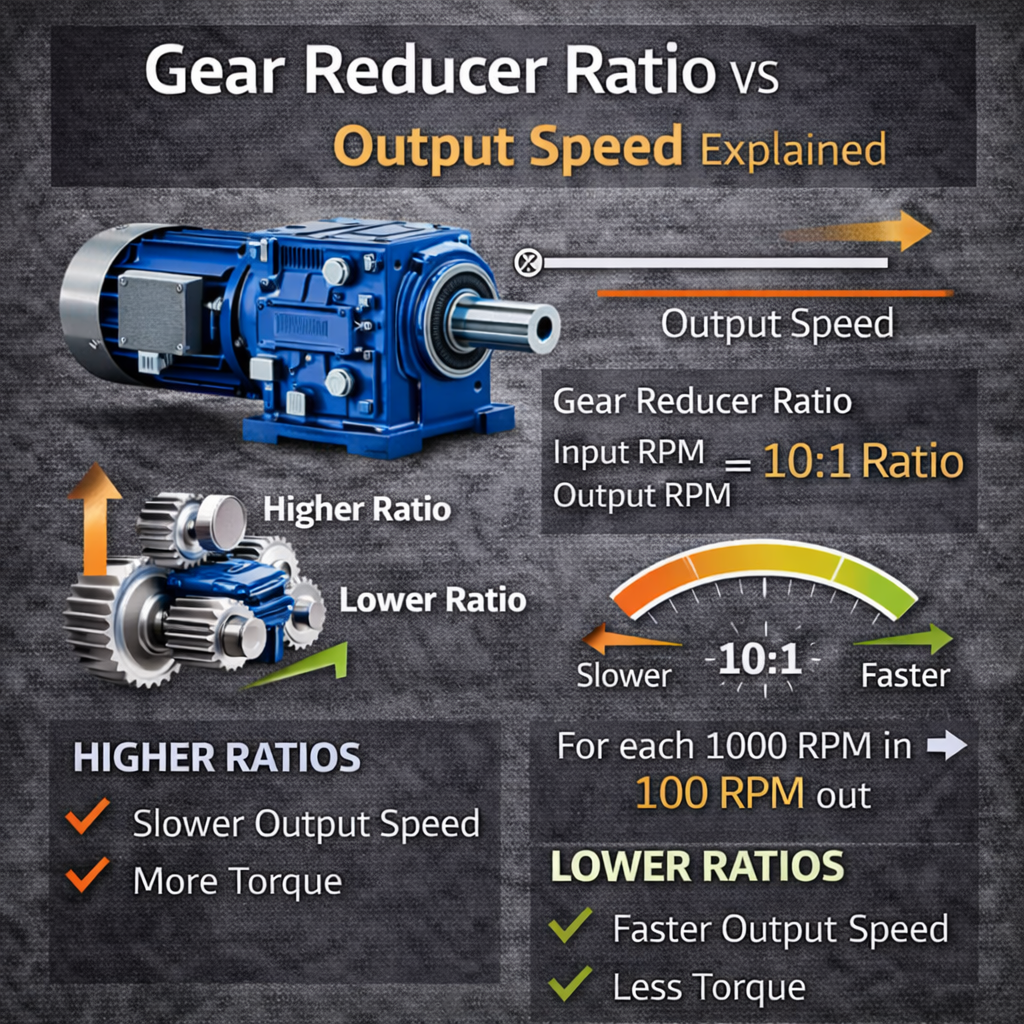
Ratio = Input Speed ÷ Output Speed
Or written as X:1, meaning the input shaft rotates X times for one output shaft rotation
For example:
A 10:1 ratio means the input shaft turns 10 times for every 1 output shaft rotation.
Higher ratios result in lower output speed and higher torque.
What Is Output Speed?
Output speed is the rotational speed of the gearbox output shaft, usually measured in RPM (revolutions per minute).
Output speed determines:
Conveyor belt speed
Mixer rotation speed
Fan or pump operating speed
Machine cycle time
Choosing the correct output speed is critical for proper equipment operation.
How Gear Reducer Ratio Affects Output Speed
Gear reducer ratio directly controls output speed.
The relationship is simple:
Higher ratio = Lower output speed
Lower ratio = Higher output speed
Basic Formula
Output Speed (RPM) = Input Speed (RPM) ÷ Gear Ratio
Example:
Motor speed: 1,800 RPM
Gear ratio: 20:1
Output speed: 1,800 ÷ 20 = 90 RPM
This relationship applies to all gearbox types, including inline, right-angle, helical, planetary, and worm gear reducers.
Common Gear Reducer Ratios and Output Speeds
Using a standard 1,800 RPM motor:
5:1 ratio → 360 RPM output
10:1 ratio → 180 RPM output
20:1 ratio → 90 RPM output
30:1 ratio → 60 RPM output
60:1 ratio → 30 RPM output
Higher ratios reduce speed more aggressively but increase torque.
Ratio vs Torque Trade-Off
Reducing speed increases torque.
As ratio increases:
Output speed decreases
Output torque increases
Efficiency may decrease slightly depending on gearbox type
This trade-off is essential to understand when sizing a gear reducer.
Single-Stage vs Multi-Stage Gear Reducers
Single-Stage Gear Reducers
Single-stage reducers:
Provide lower ratios
Offer high efficiency
Are compact and simple
Typical ratios:
Up to 10:1 or 15:1 depending on design
Multi-Stage Gear Reducers
Multi-stage reducers:
Combine multiple gear stages
Achieve higher ratios
Maintain manageable gear sizes
Typical ratios:
20:1 to 100:1 or more
Higher ratios often require multiple stages to maintain efficiency and durability.
Effect of Gearbox Type on Ratio and Speed
Different gearbox designs handle ratios differently.
Helical Gear Reducers
Helical reducers:
Handle moderate to high ratios efficiently
Maintain high efficiency
Are ideal for continuous-duty applications
Worm Gear Reducers
Worm reducers:
Offer very high ratios in compact designs
Have lower efficiency at higher ratios
Are commonly used for low-speed applications
Planetary Gear Reducers
Planetary reducers:
Offer high ratios with compact size
Provide high torque density
Maintain good efficiency
Are often used in precision applications
Gearbox type influences efficiency and heat at higher ratios.
Real-World Considerations Beyond the Formula
While the math is simple, real-world applications require additional consideration.
Motor Speed Variations
Motor speed may vary due to:
VFD operation
Load changes
Slip in induction motors
These factors affect actual output speed.
Load and Efficiency Losses
Efficiency losses slightly reduce output speed under load.
Lower efficiency gearboxes may produce less usable output power at high ratios.
Service Factor and Duty Cycle
Operating near maximum torque continuously can reduce gearbox life, even if speed calculations are correct.
Proper service factor selection is critical.
Common Mistakes When Selecting Gear Reducer Ratio
Common errors include:
Selecting ratio based only on speed, not torque
Ignoring startup and peak loads
Overlooking efficiency losses
Failing to account for VFD speed range
Choosing too high a ratio when motor speed could be adjusted instead
These mistakes often lead to overheating or premature failure.
How to Choose the Correct Gear Reducer Ratio
To select the correct ratio:
Determine required output speed
Identify motor speed
Calculate required ratio
Confirm torque requirements
Evaluate gearbox type and efficiency
Check service factor and duty cycle
Confirm mounting and space constraints
Proper selection ensures reliable operation and long service life.
Final Thoughts
Gear reducer ratio and output speed are tightly linked, and understanding their relationship is essential for selecting the right gearbox.
While the calculation is straightforward, proper application requires considering torque, efficiency, gearbox type, and operating conditions.
Choosing the correct ratio improves performance, reduces downtime, and extends gearbox life.
If you need help selecting the correct gear reducer ratio for your application, IndustrialGearboxSupply.com can help evaluate your requirements and recommend the right solution.