

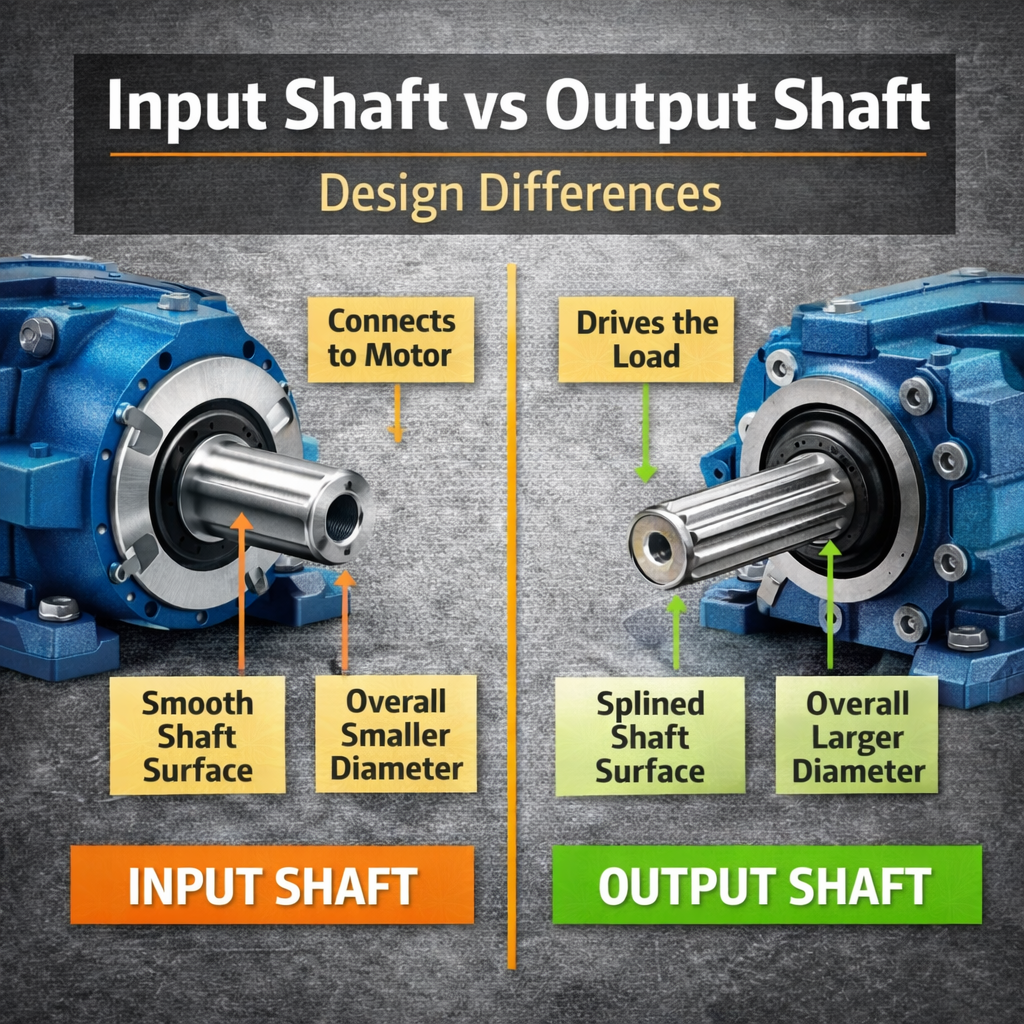
Input Shaft vs Output Shaft: Design Differences
In an industrial gearbox, the input shaft and output shaft perform very different functions. Although they may look similar at a glance, their design requirements, loading conditions, and failure risks are not the same.
Understanding the design differences between input shafts and output shafts helps prevent installation mistakes, improves gearbox selection, and makes troubleshooting far more accurate.
What Is the Input Shaft?
The input shaft is the shaft that receives power from the prime mover, most commonly an electric motor.
Its primary role is to transmit rotational energy into the gearbox so speed reduction and torque multiplication can occur through the gear train.
Because the input shaft operates at motor speed, it runs at high RPM and relatively low torque compared to the output shaft.
What Is the Output Shaft?
The output shaft delivers power from the gearbox to the driven equipment, such as a conveyor, mixer, auger, or pump.
It operates at reduced speed and significantly higher torque. This increased torque places greater mechanical stress on the shaft, bearings, and mounting interfaces.
As a result, output shaft design is generally more robust than input shaft design.
Speed Differences Between Input and Output Shafts
Speed is the most fundamental difference.
Input shafts typically rotate at motor speeds such as:
1,750 RPM
1,150 RPM
3,450 RPM
Output shaft speed depends on the gearbox ratio. For example, a 25:1 gearbox reduces a 1,750 RPM input to approximately 70 RPM at the output.
High speed on the input shaft results in lower torque, while low speed on the output shaft results in higher torque.
Torque and Load Differences
Torque loading is where design differences become critical.
The input shaft transmits relatively low torque because power enters the gearbox at high speed.
The output shaft transmits much higher torque because speed reduction multiplies torque. This torque increase places heavy torsional and bending loads on the output shaft.
Because of this, output shafts must resist:
Torsional twisting
Bending from belts, chains, or overhung loads
Fatigue from repeated load cycles
Shaft Diameter and Material Selection
Input shafts are typically smaller in diameter because torque levels are lower.
Output shafts are larger to handle increased torque and bending forces. They are often manufactured from higher-strength steel and may be heat-treated for additional durability.
Insufficient shaft diameter on the output side is a common cause of shaft deflection and premature failure.
Bearing Support Differences
Bearing selection and arrangement differ between the two shafts.
Input shaft bearings are optimized for:
High rotational speed
Lower radial and axial loads
Smooth, low-friction operation
Output shaft bearings must handle:
High radial loads from torque transmission
Axial thrust generated by gears
External loads from connected equipment
Improper bearing selection on the output shaft often leads to vibration, noise, and early bearing failure.
Connection Methods
Input shafts are usually connected to motors using flexible couplings.
These couplings accommodate minor misalignment and help isolate vibration from the motor.
Output shafts connect directly to driven equipment and may use:
Keyed solid shafts
Splined shafts
Hollow bore shafts
Shrink disc or taper-lock connections
These connections must securely transmit high torque without slipping.
Surface Finish and Wear Considerations
Input shaft surfaces are typically optimized for bearing and seal contact at high speed.
Output shaft surfaces must withstand wear at keyways, splines, or clamping areas. Many output shafts receive additional heat treatment or surface hardening to resist fretting and fatigue.
Poor surface finish or shaft damage significantly shortens seal and bearing life.
Seal Requirements
Seal demands differ due to operating conditions.
Input shaft seals must handle high speed while minimizing friction and heat.
Output shaft seals must tolerate higher torque-induced movement, potential misalignment, and external contamination from the operating environment.
Seal failure on the output shaft is a common cause of oil leaks and contamination.
Common Failure Modes
Failure patterns differ between shafts.
Typical input shaft failures include:
Bearing wear from high-speed operation
Seal degradation due to heat
Fatigue from coupling misalignment
Typical output shaft failures include:
Shaft bending or twisting
Keyway wear or shear
Bearing overload
Fatigue cracking near stress concentrations
Understanding which shaft has failed helps pinpoint the root cause.
How Gearbox Ratio Influences Shaft Design
As gearbox ratio increases, output shaft torque increases.
Higher ratios require larger output shafts, stronger materials, and higher-capacity bearings. Input shaft design changes very little with ratio because speed remains high and torque remains low.
Ignoring ratio effects on output shaft design often leads to undersized gearboxes.
Importance of Proper Alignment
Misalignment affects both shafts differently.
Input shaft misalignment typically results in vibration and bearing wear.
Output shaft misalignment causes uneven load distribution, shaft deflection, and accelerated wear of gears and bearings.
Proper alignment protects both shafts and extends gearbox service life.
Practical Implications for Gearbox Selection
When selecting or replacing a gearbox, both shaft designs must be evaluated.
Input shaft dimensions must match the motor coupling correctly.
Output shaft dimensions must be compatible with driven equipment torque, load direction, and mounting method.
Overlooking shaft design differences leads to installation problems and premature failure.
Final Thoughts
Input shafts and output shafts are designed for very different operating conditions. Differences in speed, torque, loading, bearing support, and connection methods require distinct design approaches.
Understanding these differences improves gearbox selection, installation, and troubleshooting while reducing downtime and extending service life.
If you need help identifying shaft configurations or selecting a gearbox with the correct shaft design, IndustrialGearboxSupply.com can help guide you toward the right solution.